Home » Without Label » 555 Timer Schematic - Astable Multivibrator Utilizing 555 Timer Circuit Obligation Cycle Purposes Electrician World News : In 2017, it was said over a billion 555 timers are produced.
555 Timer Schematic - Astable Multivibrator Utilizing 555 Timer Circuit Obligation Cycle Purposes Electrician World News : In 2017, it was said over a billion 555 timers are produced.
555 Timer Schematic - Astable Multivibrator Utilizing 555 Timer Circuit Obligation Cycle Purposes Electrician World News : In 2017, it was said over a billion 555 timers are produced.. The 555 is also very versatile, and can be used. Circuits into the ever increasing ranks of timer users. This led will be switched on when button s1 is pressed and switched off when button s2 is pressed. A tutorial on how to make an adjustable delay timer circuit using 555 ic that can automatically turn on/off any output after a fixed duration. A collection of 555 circuits using the 555 timer as an astable oscillator with different duty cycles.
In this project, we are using 555 timer ic to create various timer circuit like 1 min timer circuit, 5 min timer circuit, 10 min timer circuit, and 15 min timer circuit. The 555 timer ic is an integrated circuit (chip) used in a variety of timer, delay, pulse generation, and oscillator applications. 555 datasheet 555 duty cycle 555 metronome 555 reset function 555 time delay relay inverted 555 timer pulse generator. Let us discuss in detail about this circuit. The output voltage from the chip is around 1.5 v lower than vcc when high and around 0 v when low.
555 Timer Ic Internal Structure Working Pin Diagram And Description from circuitdigest.com 500ms is the same as saying 0.5s so by rearranging the formula above, we get the calculated value for the resistor, r as: Additional • timing from microseconds through hours terminals are provided for triggering or resetting if • operates in both astable and monostable modes desired. The above schematic shows the 555 timer bistable multivibrator circuit. This tutorial provides sample circuits to set up a 555 timer in monostable, astable, and bistable modes as well as an in depth discussion of how the 555 timer works and how to choose components to use with it. The time intervals can be used for keeping a relay controlled load on or activated for the desired amount of time and an automatic switch off once the delay period. Let us discuss in detail about this circuit. This led will be switched on when button s1 is pressed and switched off when button s2 is pressed. The 555 timer is a chip that can be us…
Figure 2 shows the basic 555 timer monostable circuit.
This pin connects to the negative side of the battery. 555 timer is an industrial standard ic existing from early days of ic. This tutorial provides sample circuits to set up a 555 timer in monostable, astable, and bistable modes as well as an in depth discussion of how the 555 timer works and how to choose components to use with it. The 555 ic timer circuit above shows a very straightforward design where the ic 555 forms the central controlling part of the circuit. 555 timer was first introduced by signetics corporation in 1971 as se555/ne555. 555 datasheet 555 duty cycle 555 metronome 555 reset function 555 time delay relay inverted 555 timer pulse generator. The time intervals can be used for keeping a relay controlled load on or activated for the desired amount of time and an automatic switch off once the delay period. Basic 555 monostable multivibrator circuit. Derivatives provide two or four timing circuits in one package.it was commercialized in 1972 by signetics. The output voltage from the chip is around 1.5 v lower than vcc when high and around 0 v when low. Its name is derived from three 5k ohm resistors ,connected in series used in it.the timer ic can produce required waveform accurately. Working modes of 555 timer ic. The ic can operate in three different modes such as astable, monotstable and bistable, because of which it can be adapted into many types of circuit designs like time delay circuits, pulse generation circuit, oscillator circuit and much more.
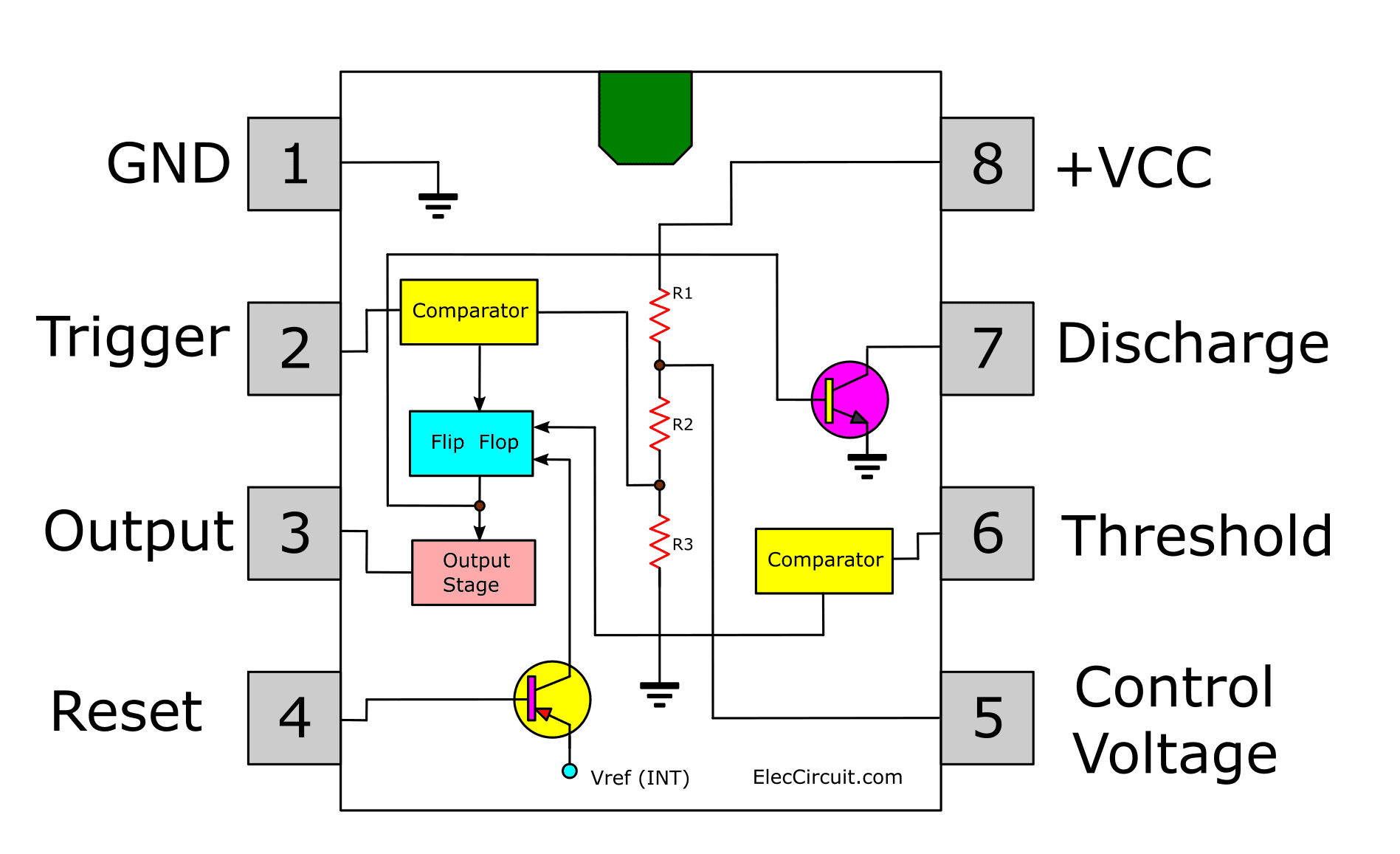
Adjustable on off timer(using 555 astable mode) in this circuit a timer with cyclic on off operations is designed. Here is the practical demonstration of the bistable mode of 555 timer ic, where we have connected a led to the output of the 555 ic. 555 ic timer block diagram 555 ic timer block diagram. Also, 555 timer is used to generate an oscillating pulse. Being an integral part of electronics project, 555 timer ic is very often used in simple to complex electronics projects.
Schematic Of Speaker With A 555 Timer With No Programming Needed from engineering.nyu.edu The 555 timer is a chip that can be us… The output voltage from the chip is around 1.5 v lower than vcc when high and around 0 v when low. The 555 is also very versatile, and can be used. Here is the practical demonstration of the bistable mode of 555 timer ic, where we have connected a led to the output of the 555 ic. 555 timer is an industrial standard ic existing from early days of ic. Here, with the help of the 555 timer ic, we are eliminating the need of manually switching on or off the device. The breadboard schematic of the above circuit is shown below. Its name is derived from three 5k ohm resistors ,connected in series used in it.the timer ic can produce required waveform accurately.
555 ic timer block diagram 555 ic timer block diagram.
The standard 555 timer ic is made of 2 diodes. Basic 555 monostable multivibrator circuit. The 555 timer ic is an integrated circuit (chip) used in a variety of timer, delay, pulse generation, and oscillator applications. The 555 timer delay before turn on circuit we will build is shown below. The ic can operate in three different modes such as astable, monotstable and bistable, because of which it can be adapted into many types of circuit designs like time delay circuits, pulse generation circuit, oscillator circuit and much more. Resistive network consists of three equal resistors and acts as a voltage divider. Simple 555 timer circuits & projects. With this information you will learn how how the 555 works and will have the experience to build some of the circuits below. Derivatives provide two or four timing circuits in one package.it was commercialized in 1972 by signetics. 555 timer circuits (133) browse through a total of 133 555 timer circuits and projects including the timer's datasheet. In this mode, the circuit of the ic 555 timer produces the continuous pulses with exact frequency primarily based on the value of the two resistors and. 555 timer was first introduced by signetics corporation in 1971 as se555/ne555. The 555 is also very versatile, and can be used.
555 timer is an industrial standard ic existing from early days of ic. Basic 555 monostable multivibrator circuit. The 555 timer delay before turn on circuit we will build is shown below. Circuits into the ever increasing ranks of timer users. The breadboard schematic of the above circuit is shown below.
How Does Ne555 Timer Circuit Works Datasheet Pinout Eleccircuit Com from www.eleccircuit.com Once this switch is pushed, the circuit pulls its output to a. 555 timer circuits (133) browse through a total of 133 555 timer circuits and projects including the timer's datasheet. There are simple circuits for beginners and advanced engineers. These on off intervals can be adjusted by varying the 555 timer output and number of counter outputs. The breadboard schematic of the above circuit is shown below. Also, 555 timer is used to generate an oscillating pulse. This tutorial provides sample circuits to set up a 555 timer in monostable, astable, and bistable modes as well as an in depth discussion of how the 555 timer works and how to choose components to use with it. Working modes of 555 timer ic.
Lm555 timer 1 features 3 description the lm555 is a highly stable device for generating 1• direct replacement for se555/ne555 accurate time delays or oscillation.
555 ic timer block diagram 555 ic timer block diagram. The values of r1 and c1 determine how long the output will remain high. Basic 555 monostable multivibrator circuit. Additional • timing from microseconds through hours terminals are provided for triggering or resetting if • operates in both astable and monostable modes desired. This pin connects to the negative side of the battery. A collection of 555 circuits using the 555 timer as an astable oscillator with different duty cycles. Once this switch is pushed, the circuit pulls its output to a. Resistive network consists of three equal resistors and acts as a voltage divider. The output voltage from the chip is around 1.5 v lower than vcc when high and around 0 v when low. The 555 ic timer circuit above shows a very straightforward design where the ic 555 forms the central controlling part of the circuit. The standard 555 timer ic is made of 2 diodes. Figure 2 shows the basic 555 timer monostable circuit. Simple 555 timer circuits & projects.